Friday, December 4, 2015

Printed Circuit Boards: Definitions

While designing a printed circuit board, some terms need to be understood in order to work with PCB design tools like DipTrace and prototyping machines like S43.

Definitions

Trace 

A trace is a current carrying path on a circuit board.

Pads

Pads are the points of contact on the printed circuit board. Pads are circular/elliptical or rectangular shapes of copper on the PCB where the integrated circuits (ICs) get attached using solder.

Via

A via is a hole that connects two layers of a PCB. It can be thought of as a jumper that connects a trace on one layers of a PCB to a trace on a second layer. 

Pads, Vias and Traces on a PCB

Base material

Base material is PCB board onto which the circuit is printed. there are many kinds of base materials available for making PCBs the most common of which is FR-4. (more details on the material properties will be discussed in the post on FR-4 material).

FR 4 base material

Solder mask

The characteristic green color of a printed circuit board is because of what is known as a solder mask. The purpose of solder mask is to protect the traces from getting oxidized. Solder mask keeps the pads and other contact points clear while the places where no soldering is required, are sealed.

Silk Screen

The writing on the printed circuit board is known as silk screen. Silk screen is used to mark the components and pads etc. on the circuit board for easy recognition. 
Green Colored Solder Mask and Silk Screen (White writing)

Single Layer PCB

A single layer PCB has circuit traces and pads on only one side of the base material. the ICs are mounted from the opposite side. 

Double Layer PCB

A double layered PCB has traces and pads on both sides of the circuit. The two sides of the double layered circuit board are connected by special type of connections known as "via". 

Multi-Layered PCB

A multi layered PCB as the name implies, consists of many layers of traces. each layers is connected to others through vias. A typical example of a multi-layered PCB is the motherboard of a computer. 

Fiducial Mark

A fiducial mark is a reference mark on a PCB whose purpose is to guide the PCB plotter to adjust its alignment. Advanced PCB plotting machines have a fiducial recognition camera that can detect the fiducial and automatically align the plotter head. The fiducial marks are not connected to any trace.
Fiducial marks on a PCB with blue solder mask

Copper Clad

A copper clad board is the base material of a PCB. The base material as explained above is made from FR-4 (Fire-Retardant 4) which is basically a mixture of fiber glass and epoxy resin. This substrate is lined with a film of copper on one side to be utilized as a PCB base material.

Routing

Routing is the arrangement of traces and pads on a printed circuit board.
PCB Routing


I will add more definitions with time. For any further information please contact saarizvi4@hotmail.com

Wednesday, December 2, 2015

LPKF Protomat S-43 Experiences: Tools used in Protomat S-43

This post is about different tools used in LPKF Protomat S43 Circuit Plotter


The tools used in S-43 can be classified into two types

1. Surface Tools
2. Penetrating Tools

Surface Tools:

Surface tools are the ones that engrave traces on the PCB by scraping copper off the base material. Three are four types of surface tools

1. Universal cutter

A universal cutter is a general purpose milling tool that can perform a wide range of milling operations. The universal cutter is 0.2 mm in diameter yet is can cut in a range of 0.2 mm to 0.5 mm. 
A 0.2 mm universal cutting tool

Illustration copied from LPKF Website

2. Micro cutter

A micro cutter is similar to universal cutter that can engrave traces in range of 0.1 mm to 0.15 mm. 


3. H.F cutter

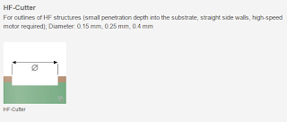
I've never used an HF cutter but by definition HF stands for "high frequency" and tool is used in applications where a high frequency PCB needs to be designed. The HF cutter cuts very neat traces with no slopes. 


4. End mill

An end milling tool is used to remove bulk copper from the board. It comes in different sizes. In a standard starter package shipped by LPKF there are three sizes of end mills available

1. 0.8 mm (1/32 inch)
2. 1.0 mm 
3. 2.0 mm

0.8mm , 1.0 mm and 2.0 mm end mills

Penetrating Tools:

Penetrating tools are the tools that punch through the PCB material by drilling action. There are two types of penetrating tools used in S-43

1. Spiral Drills

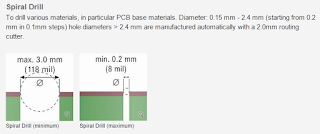
Spiral drills are the basic drills used with LPKF S43. They come in a wide range of standard sizes ranging from 0.2 mm to 2.4 mm. Holes larger than 2.4 mm are made through an contour routing tool. 

0.4mm, 0.5mm, 0.6mm and 0.7mm spiral drills


2. Contour Routing Tool

A contour routing tool is used to cut the PCB board out of the base material. 

1mm and 2mm contour routing tools


Tool Life

The tungsten carbide tools in LPKF S-43 are considered consumables. Each tool has a life span and can only work for certain number of operations after which it is rendered useless. The software "circuit pro" keeps track of the tool life. Up till now I haven't found the life of tools in either "hours of operation" or "number of operation". I will update it as soon as I find it somewhere. 


For any further information please contact saarizvi4@hotmail.com

LPKF Protomat S-43 Experiences: Construction of S43 and supporting components

S-43 is designed for fast in-house production of Printed Circuit Boards. It is as simple as operating a laserjet printer. This post will cover what S-43 looks like. Its different features and the supporting equipment required to operate this machine.

Sound Proof Enclosure: 
S-43 comes with a sound proof plastic enclosure which serves three important purposes

1. Sound Proofing 
2. Prevent fine particles produced in milling from escaping into room ventilation system
3. Helps prevent operating personnel from accidentally touching the machine while it is operating.

LPKF S-43 equipped with an FR4 Copper Clad PCB Board
Air Management System
The machine needs an air management system (A Vacuum Cleaner) for its operation. It is a necessary supporting equipment. Its purpose is to such fine particles and residue produced during the milling process and prevent it from escaping into the environment. This waste must be discarded with care as the fine particles in it are very harmful for human breathing system.
LPKF Air Management System
Hydraulic Risers: 
The cover is equipped with two hydraulic risers that keep the cover open and also prevent it from being closed abruptly. A hissing sound is common when opening and closing the cover because of the hydraulic risers.
S-43 with its cover opened

Milling Head:
Following figure shows the milling head of S-43. The head consists of a chuck for holding the milling/drilling tool. The head is capable of controlled motion in x, y and z axis. At bottom of the head there is a depth limiter whose purpose is to prevent accidental movement of milling head below certain depth as the z axis is software controlled. Any unwanted human error can easily make the milling head go beyond the desired depth and damage the tool or base material which is where the depth limiter plays its role.
Milling head of S-43

Depth Limiter for the S-43 milling head
Apart from depth limiter, the milling head is also equipped with a micrometer screw gauge which is used to adjust the milling depth and also the width (it will be explained in the future posts). 

Micrometer screw-gauge for milling depth adjustment
A tool holder is also present on the milling head. The blue conincal tool holder is used to hold tool while it is being mounted on the milling head.

Tool Support for Mounting the tool (conic thing in blue color)

Expansion/Upgrade Port:
There is an expansion port that is used when S-43 is upgraded to S-63 or S-103. The upgraded versions have features like automatic tool exchange and fiducial recognition camera.
Expansion Port of Upgrade to S-63 or S-103


Power Switch: 
The On/Off switch is located on the front-right-bottom of the machine. The is no other button on this machine - the rest is just software controlled.
Power Button on S-43


For further information please contact saarizvi4@hotmail.com


Tuesday, December 1, 2015

LPKF Protomat S-43 Experiences - Introduction to S43


This post covers some basic information about the LPKF S43 circuit board plotter.
LPKF S43 is a circuit board plotter capable of producing up to 8 layered printed Circuit boards. S43 is basically a milling machine that is able to perform following operations in its basic configuration

1. Basic Milling of Copper and Aluminium
2. Drilling
3. Contour Routing

S43 can be upgraded to advanced models like S63 and S103.

LPKF Protomat S43 Upgrade Options (from LPKF Website)

Here is good animation available on LPKF website that provides more interactive information about S43 upgrade.

Software: 
S-43 and other variants work with a software known an "Circuit Pro". Circuit pro is not a design tool. Any design that needs to be plotted, must be imported to circuit pro. I recommend to use "gerber" format.

The software used for designing the PCB include but are not limited to.

1. Dip Trace
2. Orcad


Website Links:

LPKF Home:  http://www.lpkf.com/index.htm 
Protomat S43: http://www.lpkf.com/products/rapid-pcb-prototyping/circuit-board-plotter/protomat-s43.htm 


I will cover the basic features of S43 in the coming blog posts soon.
For any further information drop an email at saarizvi4@hotmail.com